|
|
(1) Electric Fuel Pump:
The electric Fuel Pump is located at the rear of the car, external to the fuel tank. The pump operates for a few seconds whenever the ignition is switched on. This allows fuel pressure to build up before the engine is cranked. It operates continuously when the motor is cranking or running. The pump is capable of producing a pressure of 8 bar (120 psi) with a delivery of approximately 4 to 5 litres per minute which is more than required. Inside the pump is a pressure relief valve that lifts off its seat at 8 bar pressure should a problem such as a blocked fuel filter or fuel lines occur.
The accumulator is the first of the components in the fuel system after the pump. The accumulator has an important role in the operation of the K Jetronic system. The first job it has is to smooth out fuel pulses. Inside is a diaphram with a spring acting against it. Fuel pressure acts on the other side of the diaphram and causes the spring to compress. The accumulator is now charges with pressurised fuel and while the engine is running this reserve fuel is held in the accumulator and is used when surges of fuel flow occur.
The accumulators other job is to maintain pressure in the system when the engine has been turned off. When the engine is stopped and all of the non-return valves have closed, the spring pressure against the diaphram will maintain a holding pressure for about 15 or so minutes. The reason for this is that after a trip, when the engine is switched off, the temperature under the bonnet will rise which will cause the fuel in the lines to heat up and try to evaporate but maintaining the pressure eliminates this problem and ensures that the engine will start after standing hot for a short period.
(3) Fuel Filter:
This filter has a specially designed case to with-stand the high pressures of this system. You must not substitute this filter with a normal EFI one as the casing may split under the higher pressures. Due to the extremely fine internal tolerances within the K system, it is imperative that the filter is replaced with a good quality filter, such as genuine.
(4) Warm up Regulator:
|
|
Another name this is known as is the "control pressure regulator" (fuel enrichment for cold starting and altitude compensation) is mechanical and electrically heated. Basically acts like an automatic choke in combination with other components. This simple device is responsible for controlling the amount of fuel delivered to the engine during it's warm-up period. The pressure acting upon the top of the control plunger varies depending on the engine temperature and this is controlled by this device.Typical cold engine control pressure will be as low as 1.0 bar increasing over approx. 10 minutes to around 3.5 bar. Some warm-up-regulators have a vacuum connection that will sense a drop in vacuum and lower the control pressure during these acceleration periods. |

(5) Injector:
|
|
The injector on a Continuous Injection System (CIS) is as the name sugests.It flows fuel continuiously. The pintle of the injector is held closed by a spring. The pintle is only lifted from its seat if the fuel pressure is higher than the spring pressure acting on the pintle. The opening pressure of the injector is approximately 3.6 bar at which point fuel is injected. When the injector pintle opens, fuel pressure will drop, subsequently closing the injector, which causes the pressure to rise again and this will of course open the injector. This pintle vibration is called 'chatter' and helps to atomise the fuel. When the engine is switched off the fuel pressure drops below 3.3 bar and the injector closes forming a fuel tight seal, helping to avoid fuel dripping into the inlet manifold. |
(6) Cold Start Injector:
In conjunction with the Auxiliary Air Valve, Thermo Time Switch and the warm-up regulator, the Cold Start Injector asists with fuel enrichment when the engine is cold.
To aid the starting of the engine an additional injector is located into the inlet manifold, this sprays fuel into the engine at system pressure when the engine temperature is cold and the starter motor is activated. The length of time that this additional injector sprays is determined by the engine's temperature.(7) Fuel Distributor:
 |
The picture is the complete unit showing the Fuel Distributor on top and the Air flow sensor beneath. The fuel distributor meters the quantity of fuel to be delivered and distributes it to each injector. The pressure that is within the system between the fuel pump and the metering head is controlled by the primary pressure regulator, situated within the metering head. When the required pressure is obtained, the plunger within the regulator lifts off its seat and excess fuel is returned to the tank. When the engine is switched off, the fuel pump relay looses the coil negative signals that energise it and the voltage to the pump is removed: this subsequent loss of pressure will cause the primary pressure regulator to close. This action subsequently blocks the return flow to the tank and helps the fuel accumulator to maintain pressure in the system. The systems pressure is determined by the tension of the spring reacting against the plunger, if a higher pressure is required, small shims can be placed behind the spring, changing it's effective length and increasing the pressure. Located within the pressure regulator is the transfer valve. This component is operated by the movement of the plunger and opens as the plunger moves off it's seat. The transfer valve's function is to block the return flow of fuel from the warm-up-regulator back to the tank, also helping to maintain holding pressure. The lift on the control plunger will be proportionate to the air volume, this will however be exaggerated during the warm-up period when additional fuel is required by reducing the pressure acting onto the top of the control plunger. This pressure is called the control pressure (as it controls the lift of the plunger under different operating temperatures) and is determined by the warm-up-regulator. This unit delivers the correct amount of fuel to the engine via the injectors referencing to the airflow sensor plate height. As the sensor plate is lifted with inducted air volume, the control plunger is lifted proportionately, exposing small slits within the fuel distributor's barrel assembly. The barrel assembly has a series (one for each cylinder) of small slits that are machined into the barrel, and it is through these openings that the fuel passes en-route to the injector.The width of these metered slits is only 0.2 mm across and it is this dimension, together with the plunger height, that determines the fuel delivery rate to the injectors. At low engine speed the air volume into the engine will be minimal, this will only raise the plunger a small amount giving the requisite quantity of fuel for these engine conditions. As the throttle is opened and fuel demand is higher, the plate raises, which in turn lifts the plunger and a higher volume of fuel is delivered to the engine to match the air. The lift on the plunger will be proportionate to the air volume, this will however be exaggerated during the warm-up period when additional fuel is required by reducing the pressure acting onto the top of the control plunger. This pressure is called the control pressure (as it controls the lift of the plunger under different operating temperatures) and is determined by the warm-up-regulator. |
(8) Air Flow Sensor:
The air flow sensor is a very sensitive device and needs to be handled and adjusted with care. The large disc in the air horn is lifted up from its resting position when the engine is cranked and when the engine is running. Fuel flow is directly controlled by airflow through a mechanical connection to an air vane which in turn moves a plunger which regulates fuel flow. The arm connected to the disc relays its position to the fuel distributor and the Fuel Distributor then measures the correct fuel to inject. As the airflow lifts the sensor plate this subsequencially lifts the control plunger - the higher the lift the greater the amount of fuel delivered to the injectors.
To adjust the fuel mixture a 3 mm Allen key screw is located within the airflow sensor, this alters the relationship between the sensor arm and the control plunger. Turning the screw clockwise riches the mixture and vice-versa. Please note that this screw should be turned in very small increments and the Allen key should be removed before the engine speed is raised.
The airflow sensor, in most cases, is located on the air filter housing and is responsible for measuring the amount of air entering the engine. The sensor housing is conical in shape, into which the airflow sensor plate is fitted. The airflow sensor plate lifts as the throttle is opened by the incoming air.The amount of lift is proportional to the volume of air entering the engine. The shape and angle of the cone will determine this ratio.
A neutral plate position is normally level with the bottom of the cone, this
is adjustable by bending a small clip / spring that acts as a stop at the bottom
of the unit. The purpose of this spring is to allow the flap to move beyond its
neutral position to allow excessive pressure to escape if the engine was to
backfire, passing a large volume of air back into the air filter housing.
If
the system did not have this facility the pressure could split or blow off the
rubber air trunking. Any splits or ill fitting air hoses that allow unmonitored
air into the engine require rectification.
As the airflow lifts the sensor
plate this subsequencially lifts the control plunger - the higher the lift the
greater the amount of fuel delivered to the injectors.
To adjust the fuel mixture a small 3 mm Allen screw is located within the airflow sensor; this alters the relationship between the sensor arm and the control plunger. Turning the screw clockwise enriches the mixture and vice-versa. It should be noted that the screw should be turned in very small increments and the Allen key should be removed before the engine speed is raised.
NOTE :- Failure to remove the Allen key, before starting the engine, can result in damage to the airflow sensing unit.
(9) Thermo Time Switch:
The cold start injector will not inject extra fuel if the coolant temperature is higher than 95oF (35oC) Above this temperature the switch opens and no ground is supplied to the circuit therefore no cold start injection takes place.
(10) Auxilary Air Valve:
 |
A cold motor needs to idle slightly faster requiring a little additional air and fuel. This system uses an Auxiliary Air Valve, which allows a small amount of air to bypass the throttle butterfly when cold, gradually reducing the amount as the heater element warms up. This is the same as holding the throttle slightly open. The extra air by-passing the throttle butterfly is sensed by the Air Flow Sensor causing it to lift slightly higher which lifts the control plunger allowing more fuel to the injectors. This item is a device to aid the engine when cold by opening a small port to increase the engine's idle speed. The fast idle control is achieved by the port being held open by a bi-metalic strip that when heated by it's own heater element, or via natural heat soak from the engine, the port closes. The voltage supply to the air valve is the same as the feed to the fuel pump and the warm-up-regulator. If it is found that the idle speed will not reduce and that the speed is maintained artificially high when warm, clamp the rubber pipe between the air valve and the inlet manifold. If this action causes the engine rev's to return to normal, the fault is within a sticking auxiliary air valve.It is worth cleaning the valve, lubricating it and re-test it's operation. The internal heater element can also be checked for continuity using a multimeter. |
|
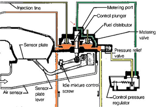
A closer look at the Fuel Distributor and Air Flow Sensor shows a better picture of how it works. Fuel from the fuel pump (orange) builds up pressure to 5bar which is regulated by the primary fuel pressure relief valve. This pressure also goes directly to the cold start injector. With engine off, no fuel flow can travel to the injectors as the control plunger has covered the metering ports into the top of the fuel chambers. A small bleed hole directs fuel to the top of the control plunger (green), then to the Control pressure regulator and then to the return line (yellow). The control pressure acting on top of the control plunger offers resistance to the plunger according to the pressure dictated by the control pressure regulator. When the engine is cold the pressure is low therefore the resistance acting on the plunger is low which allows the air flow sensor plate to lift higher. As you may now guess this will allow the control plunger to lift higher which will expose the slots in the control plunger to the metering ports which will allow more fuel to be injected. Once the engine is hot the control pressure is higher and therefore the air flow sensor will not lift as high due to the higher resistance acting on the top of the plunger. Consequently a leaner mixture is delivered. The success of the K system is entirely dependant on air flow past the sensor plate and fuel pressure and fuel flow. As a matter of interest, there are three pressures that are measured and they are system pressure (orange), Control pressure (green) and rest pressure when the system is turned off. The measurement is taken between the Fuel Distributor and the Control Pressure Regulator. Generally the fitting on top of the control plunger is removed and the pressure gauge is inserted at that point, marked with red arrow. To measure system pressure the line to the regulator is blocked. This is acheived by using the correct gauge. When the line is opened control pressure is measured. When the engine is turned off, rest pressure is measured. The return port in the pressure relief valve is closed so maintaining rest pressure is now accomplished by the fuel accumulator.
|
|