The instructions that follow are not exhaustive. Covering every possible test procedure is not in the scope of this article. It deals with basic sensors from the late1980's when they were first introduced in Australia. I have the test procedure for the most common sensor from those days. I would advise that if you are checking fairly late model sensors that you refer to the manufacturers workshop manuals or obtain at least an up to date copy of a Gregory's Fuel Injection manual or similar. The oxygen sensor is an important part of the fuel management system, but only part of the system, and therefore before testing the oxygen sensor circuit, you must be sure there are no other engine problems and that all emission devices work and engine sensors are functioning correctly. The O2 sensor is the primary device that the engine management system relies on to make fuel corrections so it must be in good working order, so after verifying that the sensor is good and you still have fuel consumption or surging problems then the fault will be somewhere else. Try using the EFI diagnostic charts in the Fuel Injection section, they may steer you in the right direction.
The operation of the O2 sensor should be checked any time there's an emissions or engine performance problem. The sensor should also be checked when the spark plugs are replaced, remember they are a maintanance item and will need to be replaced after the recommended period. The best way to test an O2 sensor is by using a scan tool plugged into the OBDII socket, the next best is an oscilloscope while the engine is running at operating temperature and the DIY home mechanic will need to use a digital multimeter with bar graph. Using a multimeter or scope you will need to backprobe the sensors or the ECU if you know the terminations.
|
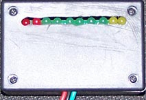
Following is a quick reference to knowing the wire layout at the sensor: (zirconia sensor)
|
|
|
|
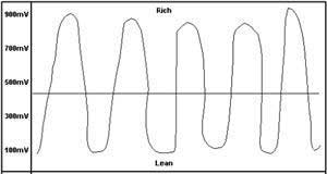
This is the scan tool pattern of a good sensor |
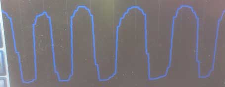
Run the engine up to 2000RPM and block the throttle. A good sensor will output a voltage oscillating between 0.1 and 0.9 volts more than 3 times per second, similar to the diagram & actual photo above if using a scan tool or oscilloscope. A digital voltmeter will tell you if the sensor is producing a signal, but not if the signal is a good one because the numbers change to quickly with higher transition rates but the bar graph movement may be useful and you should get a good idea from this. A quick rap of the accelerator should give an instant response of a high voltage reading and a low voltage when decelerating.
You can make the fuel mixture artificially rich by feeding LPG into the intake manifold, this should cause the sensor to respond immediately and go to maximum (above 0.8v) output. Creating a lean mixture by removing a vacuum line should cause the sensor�s output to drop to its minimum value (below 0.2v). If the sensor voltage does not oscillate quickly enough, it needs to be replaced. In later model cars with an O2 sensor fault code available, a sluggish sensor often won�t set the fault code, so don�t assume the sensor is OK if there is no code.
An O2 sensor that outputs a steady low voltage or steady high voltage while holding revs constant may be faulty or is not actually running in closed loop. When voltage starts to vary up and down then the sensor has entered what is known as closed loop and this is when the output from the sensor contributes to the fine control of the amount of fuel injected. The O2 sensor will not enter closed loop when the engine is cold. A faulty coolant sensor as an example can stop the system entering closed loop. As I said at the start, you must make sure all other sensors are working correctly.
The sensor can also be checked by removing it from the vehicle but I recommend on vehicle testing if possible, it is much easier than removing sensors to test them. Connect a digital voltmeter to the sensor and use a propane torch to heat the sensor element. With a zirconia sensor, connect the positive test lead to the sensors output wire, (usually black) and the negative test lead to the sensor housing ground or the earth circuit wire. Either holding the sensor with pliers or a vice, use the propane torch to heat the sensing element. The flame consumes most of the oxygen, so the sensor should generate a high voltage of about 0.9 volts within a few seconds. Next, remove the flame while observing the voltmeter. The sensor reading should drop to less than 0.1 volt within a second if the sensor is good. If the sensor has a heating element you can test it as well, connect a multimeter set to a low Ohms reading across the sensors two heater wires. If the heater circuit is okay, the meter will register a resistance. It doesn't matter what it is as long as it is not an open circuit (infinity Ohms).
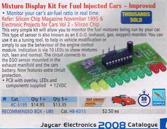
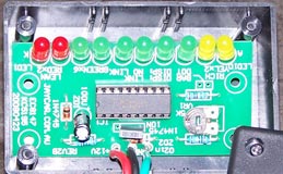
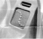
So you haven't got a scan tool, scope or multi-meter, then here is a simple little device you can make yourself. It is a Fuel mixture display kit that can be purchased from Jaycar Electronics. You can make it a stand alone tester as I have done or you can mount it permanently in your car which enables you to monitor your mixture whenever you choose to look at the display. Remember once in closed loop the display will oscillate back and forth, should look pretty cool. But if you think this might distract you, make a cover that can be easily removed or simpler yet, mount a small switch in the red power wire so you can turn it off when not required. There is a small potentiometer fitted on the circuit board that will need to be adjusted, so allow for this before fitting it permanently. All the instructions are in the kit.
|
|
|
Nice neat installation into the dash resembling the curve of the O2 sensor voltage. |
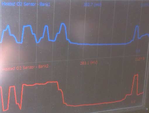
To finish off I have screen saved a few sensors on my scan tool to show what bad sensors look like.
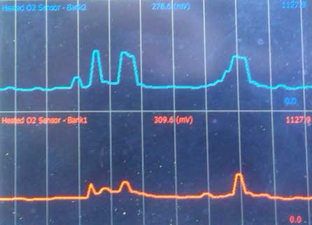 |
Pretty much almost totally stuffed. Showing mostly a lean mixture with a small response every now and then. The ECU will want to richen the mixture with these sensors causing poor fuel economy and early catalytic converter failure. |
| Slightly better, at least we have some attempt at oscillating. One side is doing better than the other but no where near to what the waveform should look like. Once again long term use of these sensors will shorten the life of the converter. | 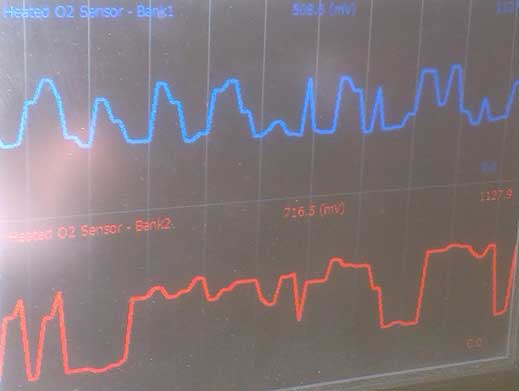 |
 |
The same sensors as to the left but this time the accelerator was snapped open. The mixture registered lean & stayed that way for a few seconds before starting to slowly recover to the way it was. These sensors need replacing. |