BACK to TECH TALK

Ford Cleveland Roller Rocker Conversion

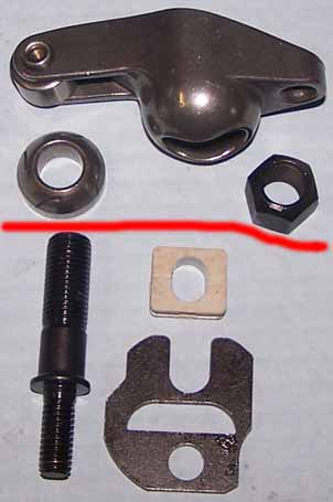
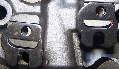
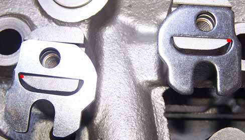
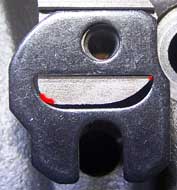
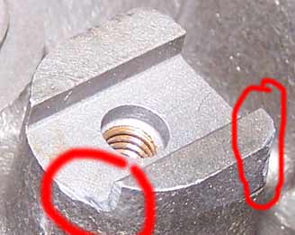
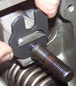
Recently I had the opportunity to convert a 302 Cleveland engine over to roller tipped rocker arms. To do this however you need to install a stud conversion kit as per the photo to the right. The bits required are below the red line. This kit is manufactured by Crane Cams. Was I in for a surprise. I would have thought that the conversion would be very straight forward but I was wrong. The instructions that came with the kit was a little incorrect in relation to the orientation of the 
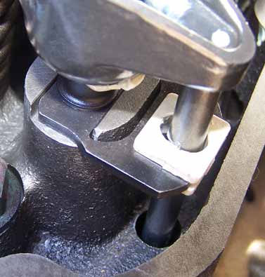
guide plates, but brushing this aside everything else in the instructions was pertinent to the installation. To get to the crux of it, basically the guide plate orientation is not the same for inlet and exhaust. The exhaust are fitted opposite to the inlet or visa versa. The instructions blame core shift for this, but in fact this has nothing to do with it.

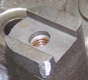
The kit includes the 7/16" stud, the guide plate bracket and the push rod insert. A small tube of Loctite is also included to lock the stud into the threads of the pedestal base.

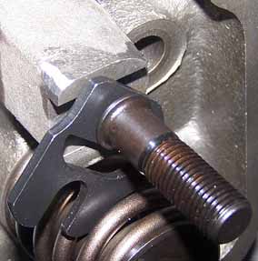
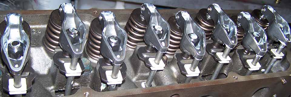
The rocker pictured is a ProComp 1.72:1 ratio 7/16" roller tipped rocker. This is purchased seperately if this is the type of rocker you desire or you may go for the full roller rocker. They both will fit this conversion kit, but remember to purchase 7/16" rocker arms.

To fit this kit you will need a small electric grinding disc attachment similar to a Dremel as only small amounts need only be removed from the pedestal posts to fit the guide plates.

When I started to fit this kit, I already had one head assembled to the engine. The other head was on the bench. Thinking the kit assembly would be straight forward, I proceeded to fit the kit to the head on the engine. 10 seconds later I realised some grinding of the rocker posts was required. After a bit of swearing, I calmed down and thought of a way to do this without contaminating the engine with metal filings. Using a large piece of contact, I was able to cover the entire head and block. I simply cut a slot in the contact above each pedestal and forced the plastic around the post till it was below the pedestal base and sticking well. The ones that did not stick, I wrapped sticky tape around it to hold the contact tight against the post. This gave an excellent seal and all metal filings from the grinding disc were directed over the contact and not into the engine or cylinder head area. When finished, I simply blew the metal off the contact and removed the contact from the head. Job done.

The first step is to place the bracket on the pedestal. You will definitely see that the inlets are oriented differently (the one on the left is way off, so flip it over. You can see the exhaust one is not lined up with the stud hole. It is close but not close enough. The stud will not screw into the thread unless the holes are lined up. The little red dot indicated where some material must be ground from the post to allow the bracket to move over to the left a bit.

Ok, I have flipped over the inlet bracket and it too did not quite line up. The red dot area indicated where material must be removed.

Right photo: Here is another that required grinding on the thick side of the post and also a very small amount from the thin side.


This one required grinding on both ends to fit the bracket correctly. Note that the grinding must extend down to the base, otherwise the bracket will not sit flush on the base. You may be able to screw the stud down tight and force the bracket to sit flat but all you do is stress the bracket and it may split at that point of interference.

After grinding the small sections, screw the stud in and allow the bracket to hang.. Then lift the bracket and place it into position. It should go on easily and sit flat against the base and even have a little lateral movement for good measure. If you meet this criteria, then you are ready to install this rocker stud. As a matter of course, I fitted each one individually. Each bracket had its own position on the head.


In the kit you are given two nuts to lock onto the stud so it can be screwed in tight. Loctite is fitted to the threads to lock the stud, this is included with the kit.

Close up of one rocker arm fitted showing clearly where the post has been ground.

NOTE: You cannot install all the brackets if the head is not fitted to the engine. Some cylinder head bolts will not fit on past the bracket. This kit can only be fitted with the heads installed on the engine.

Crane recommends to fit allen head cap screws in the top row to replace the original head bolts. This way the heads can be removed without removing the guide plates. This makes real good sense if you think you will be removing the heads several times and also if you will need to re-torque the cylinder head bolts. A socket will not fit on. Otherwise you will need to remove the rockers & studs and then re-assemble them and re-adjust the lifters. A lot of work. Purchasing allen head cap screw bolts would be much easier.


One head completed and rockers installed but not yet adjusted.

Not all the posts had to be ground. Out of 16 posts, I was able to fit 4 straight on. This is not a difficult job and the material that is removed is only minor. It is a nice conversion to roller tipped rockers but you can fit the full roller kit instead if desired. This conversion only fits the stud and push rod guide bracket, what rocker you want from there is up to you.