OSM Hompage


BACK to CARTER

Thermoquad TQ

Suits Models:

Ford Bronco & XLT   1981-85    5.8L

Ford F100 F350 F500 F600   1977 on   5.0L  5.8L

Falcon GTHO  XC - Cobra   1976-12/78     5.8L  351ci

Fairlane ZF ZG ZH ZJ ZK       302/351ci

Falcon Fairmont  XA XB XC XD XE   1976-3/83     302/351ci

LTD  ZH ZJ     5/76-77     351ci

LTD  FC FD   6/79-3/83    302/351ci

This huge carb came out on the Ford V8's, 302 & 351. Not that difficult to re-build, but it needs to be adjusted correctly to do a satisfactory job. Unfortunately this is not the case in many rebuilds, so the carby got chucked in favour of a 600/650CFM Holley carb, with no real advantage gained. In my opinion it is easier to adjust a Thermoquad than a Holley. For the stock engine to a mild performance re-build, you should consider keeping the TQ. Just make sure you find a tuning specialist in your area that knows how to adjust and modify it. The instructions that come with a Fuel Miser carb kits do not have all the critical linkage adjustments anymore as it once did. You will need a factory service manual to accomplish this.

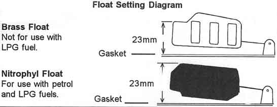
The Nitrophyl floats can sometimes get heavy from fuel saturation as they are made from porous material coated with a sealer. Do not damage the surface as this will render the float useless & consequently the carby will most likely flood because the float will not be able to apply sufficient force on the needle & seat to stop the flow of fuel. Incorrect adjustment of linkages is a common problem after the carb has been rekitted a few times by the inexperienced. Correct adjustment of the main metering rods are critical for proper operation and might need the services of a dyno tuner to adjust them to the correct position for economy as well as the tension on the secondary butterflies for smooth power, but these can be done eventually over time by trial and error.

The top gasket needs to be in place. With the top inverted, measure the distance from the bottom of the float to the carb top. It should be set at 23mm. To adjust the measurement bent the arm of the float.

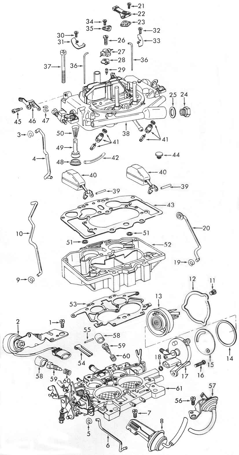
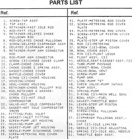
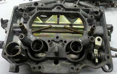
Start with the base. Grease the metering rod lever #54 & cam to stop wear of the lever & fit it into place. Fit the gasket to the bakerlite body & fit the body onto the base, then proceed to assemble the top.

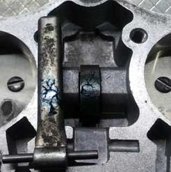
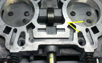
This carb was modified because the idle could not be set low enough. There are 2 holes in the discs that were solderd up & 2 vacuum passages that had lead shoved into them, both marked. It was later discovered there was a vacuum leak. Once the vacuum leak was fixed they once again had trouble adjusting it. hence I got it to repair. In this carb the lead would have had no affect whatsoever as the passages are not in use, but the disc holes will affect idle & progression & therefore I removed the solder  and returned them back to standard. Adjust the mixture screws back from fully in 2 turns out.

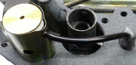
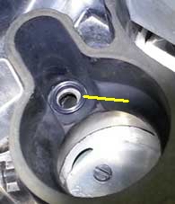
Screw the needle seats in, fit the new vent valve. Install pump plunger spring, large end first then the pump plunger. Hold in place with the S link #47. Then fit the bottom check valve & tap into place. Now fit the gasket & the rest of the needle & seats & set the float levels. You will need to raise the gasket to fit the float pins.

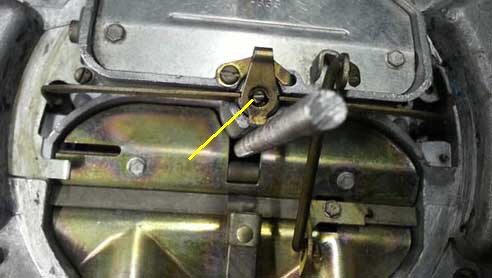
When all is done the final step is the pump housing cover then the pump passage tube over the accelerator pump housing & squirter. Do not kink the tube. Before fitting the top over the body install the main metering well seals into the primary main well cavities in the bakerlite body. As you lower the top down ensure the Y linkage mates up correctly to the vent linkage (marked yellow). The linkage must fit into the Y section of the fork.


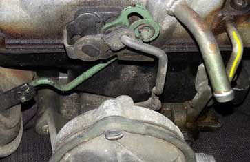
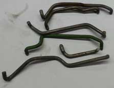
Now for all those linakages that got removed. These are not all of them, depends how far you stripped it down. Hopefully you took some pictures but that does not mean it is correct. Check out all the pics I have supplied & fit your linkages the same.

Just a few little bits to go. The accelerator pump shot weight & housing. The metering rod plunger & rods, do not force the rods in, they bend easy. Choke housing & hot air compensator over the second barrel.

Main metering rod is adjusted once correct idle mixtures and idle speed are set.

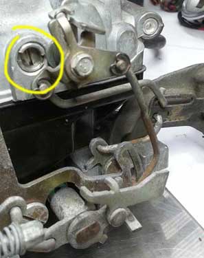
Shown is the secondary tension adjuster. Playing with this will bring in the second stage earlier or later. Make sure all the other linkages are adjusted correctly first, idle mixtures set & main metering rod are all adjusted correctly before making changes here.

If you look closely at the photo you can see at least 4 links that can be bent to adjust certain aspects of the linkage operation. That is not to mention various linkage tags that can be bent as well to achieve different settings. The mind boggles at all these adjustments but when they are spot on the carby is quite awesome in operation.