|
|
||||
|
|
|
|
Carburettors - Basic Theory |
|
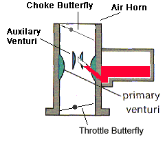
The carburettor consists of an air passage, called the throat or barrel with an integral fuel chamber. On the air intake end of the throat is a choke valve (choke butterfly) and on the manifold end is a throttle valve (throttle butterfly). In between these two valves is a primary venturi and an auxilary venturi which is the most common configuration for a downdraught carby.
These valves and the venturi provide what is needed to draw fuel from the fuel chamber into the airstream passing through the throat of the carby to the engine intake manifold. To move the fuel from the fuel bowl to the intake manifold we need to create a pressure differential between the space above the fuel in the fuel bowl (via a vent to atmosphere)and the outlet into the auxilary venturi. Every time the piston is on the induction stroke it creates a pressure differential between the cylinder and the atmosphere outside the carby. The air pressure outside the carby is greater so it pushes the air through the carburettor and into the engine. As the air passes through the carby venturi it creates another pressure differential which causes the fuel to be pushed into the airstream through a discharge nozzle. The design of this nozzle and the low pressure in the venturi, help to atomize the fuel as it is mixed with air. The throttle butterfly is located at the manifold end of the barrel and is controlled by the accelerator pedal. The butterfly acts as a restriction to the air flow through the carby. At closed throttle the manifold vacuum is high but air speed is low and fuel delivery is small. At wide open throttle intake manifold vacuum drops and fuel flow is high. The throttle butterfly in essence controls the amount of air entering the engine, now we have to get the correct amount of fuel in the right proportion to the air passing through the carby. To accomplish this there are several circuits in a carburetor that have different roles to play in delivering an accurate air fuel ratio under all operating conditions. If there is a problem with any one, it will impact partially on the next circuit. The circuits are:
Float Chamber / Float Bowl: The float chamber / float bowl or fuel bowl as it is commonly known is nothing more than a reservoir for the fuel. The fuel bowls fuel level is held at a constant height by the needle and seat. A float is hinged inside the bowl and when the fuel reaches a predetermined height the float presses again the needle valve and shuts off the fuel supply to the bowl. As soon as the level drops the valve is allowed to open and more fuel is delivered into the bowl, therefore the float is constantly maintaining the same level in the bowl regardless of engine demands. The float level height is very important for the correct operation of the main and power circuits. To high a level and fuel droplets will discharge from the discharge nozzle too early and therefore cause a rich mixture. Too low a level and the fuel discharge will be delayed which may cause a lean surge or stumble in smooth engine acceleration.
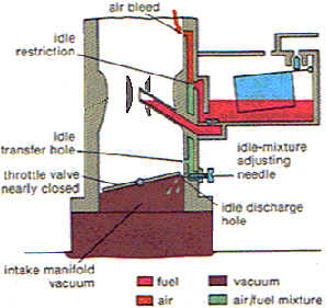
Idle: The purpose of the idle circuit is to supply the correct A/F ratio for idling purposes. When an engine is idling, there is not enough air velocity through the venturi to create a pressure differential strong enough to draw fuel from the discharge nozzle at the auxilary venturi, so another means of fuel supply is necessary for the engine to idle. The idle circuit supplies fuel when the throttle butterfly is slightly open as in the idle speed position. Mixture screws let you adjust the mixture of this circuit. The fuel is delivered through a small hole in the base under the throttle butterfly which is subjected to high manifold vacuum and therefore fuel will flow from the discharge opening. Idle circuit metering is accomplished by four things: Idle restriction (idle jet), idle air bleed, idle progression holes and the idle mixture screw. As fuel is drawn past the idle jet it is mixed with air entering through the idle air bleed. It then travels down the idle circuit passage and as it passes the idle transfer hole or progression ports more air is mixed with the fuel. The mix of air and fuel then passes the idle mixture screw and out the idle discharge hole where it is mixed with the air passing the throttle butterfly. The adjustable idle mixture screw regulates the mixture for a smooth engine idle.
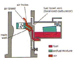
Progression: When the throttle is opened to increase engine speed, more fuel is required as more air is drawn into the engine. The progression circuit supplies fuel between the idle and the main metering system. This is a small slot or series of small holes that are uncovered as the throttle is progressively opened above the normal closed butterfly position. The idle transfer hole/s are now gradually exposed to manifold vacuum and the extra fuel mix is drawn through these holes. The amount of fuel is determined by the idle transfer hole size restriction in the base and are set by the manufacturer and should not be tampered with under normal conditions. Depending upon the size of the engine, the RPM and load the engine is under, you can still have flow from the idle and progression circuits well into the higher rpms ,although this flow will be greatly reduced. This is due to the restriction of the main venturi causing a pressure differential below the venturi. If you have a carby that is too small, then at Wide Open Throttle (WOT), you will still have sunstantial manifold vacuum. Manifold vacuum is what pulls fuel from the idle and progression circuits where the idle discharge hole and transition hole or slots are. So as long as you have reasonable manifold vacuum, the idle circuit and progression circuit will be flowing fuel but very much diminished. Main Metering: As the throttle butterfly is opened above idle a pressure drop is created by the main venturi. This pressure drop is increased by the auxilary venturi and since the pressure in the auxillary venturi is less than the pressure acting on the fuel in the fuel bowl, fuel is caused to discharge from the discharge nozzle (emulsion tube). The emulsion tube and the auxilary venturi (booster venturi), supplies the major portion of the fuel at cruise and power levels. Metering of fuel is accomplished by the main jet and air bleeds (air correction jets) or a metering rod and air bleeds. Same as the idle circuit, air enters through the air bleed and mixes with the fuel which helps to break up the fuel into tiny drops so that the fuel mixes better with the incoming air stream and is fully atomised once it is drawn into the auxilary venturi.
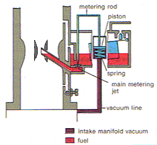
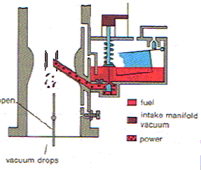
Power System: As engine load increases however, the main circuit cannot supply sufficient fuel for the purpose of increasing horsepower. Extra fuel is required and this device is activated by engine vacuum or more accurately lack of it. The power valve simply opens and closes at a preset amount of manifold vacuum. The valve is best set to activate around about 8.5" Hg of mercury. The lower the number, the later the valve opens, the higher the number, the earlier the valve opens. In systems that use the metering rods there is no separate power circuit. This is controlled by the position of the rods in the main jet. The tip of the metering rod is tapered so under high vacuum the rod restricts fuel flow but when vacuum drops the rod lifts out of the main metering jet. At this position the rods are thinner thereby allowing more fuel to pass through the jet.
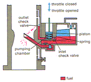
Accelerator Pump: Supplies fuel under pressure to compensate for losses in fuel flow when the airflow signal to the booster venturi diminishes when you punch it from a standstill, or when the airflow goes away during changes in engine load. Another reason an accelerator pump circuit is required is due to the heavier weight of the fuel. Although the pressure differential at the venturi responds to load changes quickly the extra fuel required does not respond at the same rate as air flow, therefore an extra shot of fuel is required quickly to avoid any hesitations in engine response. The inlet check valve allows fuel to enter the pump chamber when the pump piston is lifted. The outlet check valve on most carbies is below the squirter nozzle. It consists of either a small ball held down by a steel cylinder, or a sharpened steel cylinder. The outlet check valve is required to stop siphoning by the airflow going through the carb throat. Any downward movement of the pump plunger causes the inlet check valve to seat and block the fuel from going back into the fuel bowl. It is therefore forced to travel along the pump discharge passage. The pressure from the downward movement lifts the outlet check valve and allows the pressurized fuel to squirt into the venturi area as a fine spray.
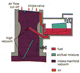
Choke: The choke is a simple enough device. It is a valve placed in the air passage of the carby in the air horn area and when activated, will close off the incoming air, which will make the mixture richer for easier cold starting and more even running and idling when cold. If an engine could be heated up to operating temperature before you started it, you would not need a choke. For those disbelievers that don't believe in chokes and disconnect them, try this experiment. Pump the accelerator only once, start the engine and immediately let it idle. I guarantee it will take longer to start and near stall when you let it idle. I bet you have to keep feathering the accelerator for about 15 secs or more to keep it running. If however the engine starts and runs well, I would suggest the carby is not set-up correctly. In all my years as a tuner, I have never come across an engine, when tuned correctly was able to idle, when cold, without assistance from the driver to keep it idling if a choke was not fitted.
Well I think I will cut it off here. I certainly have not explained everything there is to know about how a carby works, after all this is only basic. There is a lot more to it as the carbies get more complicated to comply with stricter pollution regulations. I believe I have covered the basic circuits involved in a way that most will understand without getting to technical. |