|
|
|
|
Introduction:
|

|
| |
Before we go into the assembly, I will just cover in brief the history of this engine as substantial damage was caused by poor dismantling and assembly in the first place. It may be an idea to read my article on Indexing a Crankshaft to be sure that the crank is not twisted. Part 1 Critical Engine Measurements in the Engine section has the dis-assembly of this engine explained and should be
read to get an idea of what can happen when poor dis-assembly techniques are used. If your engine is on the first rebuild or you have genuine Honda bearings fitted, please take note of the previous article mentioned. I will further add that this engine has had major machining work carried out since dismantling. Unless your engine has also had the same work performed then some of the procedures in this article will not pertain to your assembly. The reason is that I am using aftermarket main and big-end bearings
because the crank and block have been machined to accept them. You will understand more once you read my other article, so I am not going to cover assembly using genuine bearing shells.
This engine luckily was able to be saved by the skillful work of the machinists at HM Gem Engines, Townsville. The block needed line boring, due to the spun main bearings. HM Engines managed to reduce the crank centre line offset by only .002". What does this mean? Basically the crankshaft is sitting in the block .002" closer to the deck surface which means the piston deck height is reduced by the same factor. This will result in a very minor increase in compression ratio which is negligible.
I was expecting a figure of around .005 - .010" which would have probably required the fitment of a thicker head gasket to ensure the piston would not touch the cylinder head or valves. The crankshaft was machined to .020" undersize on the mains and .010" on the big-ends. The conrod big-ends were resized back to standard bore size to accept the aftermarket bearings. If you read my other article, you now understand that I can use aftermarket bearing sets. This makes assembly so much easier.
Also understand that flex-honing of other components other than the cylinder bores is not absolutely necessary. I use them because I have them available and they add that touch of perfection to my work from the benefits they provide. The results from flex-honing various other components are shown in another article in the Engine section. Very early in my career I became very aware that assembling engines with bare hands was not a good idea. Your hands perspire and the sweat passes
off onto any metal you have touched. This will cause rapid onset of surface rust which is detrimental to all the hard work that you are putting into the assembly. I always use latex gloves once I am into the assembly phase of an engine and you should consider doing the same.
Before you start any engine assembly, you must of course have available a specification sheet of all clearances and torques. Otherwise the re-build can't happen.
It
is a proven fact that when an engine is first started up (new or old), there is a short
period before the oil in the crankcase can properly lubricate all the moving
parts. During the start up period, high heat is developed and scoring of moving
parts takes place. A thin film
of extreme pressure lubricant (pre-lube) has sufficient anti-seize
properties to overcome this condition and it simply dissipates into the oil once the oil begins to circulate
through the engine.
|
|
|
Preparing the Block
|
|
| |
|
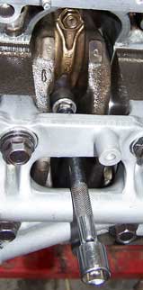
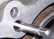
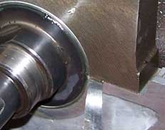
Good block preparation is essential. If you have had machine work performed then the block may have been acid cleaned for you which makes the job of cleaning much easier. All that is required from you is to remove any metal particles left behind from the maching process. My first step is initial oil gallery clean. This is too easy in this engine as there is only one passage up through to the deck. The rest of the oil galleries are in the main bearing cap girdle. Brushes are a must for
successful cleaning as pressurised air alone through the galleries may not remove all the metal. Run a thread chaser on all the internal threads on the mains and head bolts otherwise under torqueing may occur which will lead to failure of the main bearings or head gasket. The threads on the mains and head are recessed quite deep into the block as can be seen on the bottom photo. I had to make a special adaptor which allowed the tap to go deeper into the block.
|
|
|
|
|
Honing the Bores
|
|
| |
|
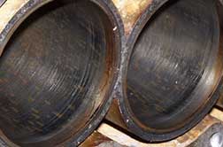
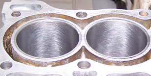
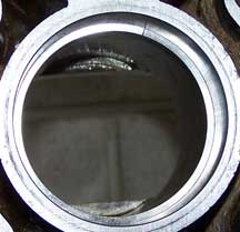
Once the block and galleries are clean, finish off with the hone job and then another quick clean of block internals and then lastly the bores. I DO NOT use the soapy water method of cleaning the bores. I initially use copious amount of Brake-Kleen then I use a can of spray cleaner that does the job much better and with no rust formation afterwards. I don't need to go into it, I covered it in the flex-hone article. (top photo)Whoever honed this bore last did a horrible job of it. The crosshatch angle is
totally incorrect for proper ring seating and oil control. The stroke movement of the drill was too slow for the speed causing a very shallow crosshatch of I guesstimate about 5 deg, instead of 45 deg, the ideal included angle as recommended by most engine manufacturers. |
|
|
|
| Main Bearing Crush |
|
| |
|
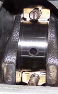
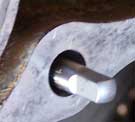
Although it is unlikely that you will receive faulty manufactured bearings, you still need to check each cap & cradle for the correct crush. To check crush you simply fit and torque the main girdle with the bearings fitted. Be sure to wash the protective coating from the backs of the bearings before fitting them. Once torqued, loosen all the bolts on one side of the girdle. As seen in the photo, try to insert the largest feeler gauge possible just to the side of the bearing. You
need between .006" & .008". What if each cap varies, what does this mean? It could mean several things (1) faulty bearing or (2) tunnel incorrect size. How do we distinguish which it is? Lets say that #3 main has less or more crush than desired but all the rest were acceptable and within specification. The simple thing to do would be to swap this bearing set with another and re-measure. If the crush is unchanged then the main tunnel is out of spec and possibly needs to be line bored. If the #3 crush
changes, then there is variation in the bearing set. To rectify this you may need to swap shells around until you get each journal crush within spec. If this fails then you will need to get another set. The same principal applies to the big-end bearings as well. It shouldn't get to this as the main tunnels should have been measured earlier and rectified as necessary.
Here is some maths for you. A main bore diameter of 2.375" has a bearing crush of .006". If the diameter was increased by only .001", that would be enough to reduce the crush to under .003" which of course is under specification and the risk of bearing spin is increased. Therefore the tolerance for tunnel diameter variations is no greater than .0005" for out-of-round and .0002" Max for taper.
|
The photo I took with the crank out was to blurred to use so I had to retake the photo after I assembled the crank. Crush was spot on at .007"
|
|
|
| Prepare Crankshaft & Fit |
|
| |
|
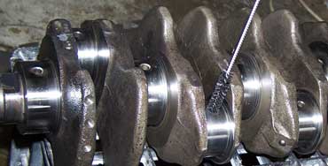
Any machining process produces metal shavings and the possibility of these shavings ending up in the crankshaft oil gallery holes is very high and therefore requires to be thoroughly cleaned. Using a small brush, push it through all the oil gallery holes while cleaning solution is running over the crank. Then dry off with compressed air. I like to always use Brake-Kleen or similar product to do the final clean and then use compressed air. Ensure you apply plenty of assembly lube
to the main bearing cradles & thrust washer before you fit the crank in and then plenty of pre-lube on the girdle bearings.
|
|
|
|
|
Checking Oil Clearances
|
|
| |
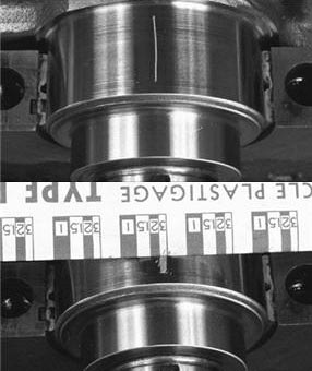 |
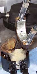
Flexi-gauge is probably the easiest way to measure bearing oil clearances. Let's face it, you probably won't have all the measuring tools required to do it any other way. I personally rarely use flexi-gauge. On this engine I measured all the journals and tunnels with bearings fitted while I was checking bearing crush. To use the flexi-gauge method on this engine entails removing the main cap cradle again which is quite tedious and awkward. It is easier to measure the journals,
tunnels and bearing shell thickness and do a little maths to get the clearance. To the left is a sample of what flexi-gauge looks like. The small piece of gauge, is placed across the crank journal (top of photo). When the girdle or main caps are torqued the flexi-gauge is squashed slightly depending on the clearance. The caps are removed and the gauge will either be stuck on the crank or the bearing. It is a simple matter of using the guide to measure the spread of the gauge. You can see that if the clearance
is only .001" the gauge is flattened considerably. (These photos are not from this engine)
|
|
Remember to fit the oil feed "O" ring on the centre girdle before the final fit of the girdle.
|
|
|
|
Final Torquing & Rotation Test
|
|
| |
With the main cap girdle re-fitted, put a few drops of oil on the bolt threads and some pre-lube under the bolt head & washer. The two longest bolts go on the centre cap. Torque it down in two steps as per the spec sheet. If you have ARP Ultra-torque use it instead of oil on the treads & bolt heads. The torque settings are far more accurate using the ARP product.
|
|
|
Fitting Rear Seal
|
|
| |
Never use a hammer or punch directly on any seal to install it. I put a thin smear of stag on the outside of the seal to ensure it would not leak and then used a block of 3 x 2 hardwood on the seal to get it into the housing and improvised a tool to get it further into the housing until it seated. Apply grease to the seal lip and to the mating surface on the crank. Apply a thin smear of sensor safe silicone to the joining face and fit the seal housing, torqueing to specs.
|
|
|
Install Flywheel & Check End Float
|
|
| |
|
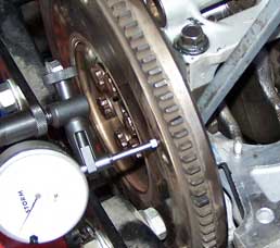
Make sure you have tightened the oil gallery end bung before fitting the flywheel. Put one drop of Loctite on the thread of each flywheel bolt and torque it up.
Either using a dial gauge or a feeler gauge, you need to measure the end float of the crank. Push the crank to one side and then to the other side to help seat the thrust washer. Read the end play directly on the dial gauge. If using feeler gauges then measure the gap between the trust and crank when the flywheel is forced to one side.
|
|
|
|
|
Check piston ring lands, ring gaps in bore
|
|
| |
|
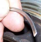
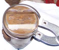
Before any rings can be fitted to the pistons, the ring lands need to be cleaned. This is simply achieved by using an old ring. Break or cut a ring in half and grind the end to a sharp point. Ensure the sides are filed after grinding other wise the sides of the ring land will be cut when you try and clean the land. It is a simple matter of forcing the ring around the ring land to clean any carbon out. Make sure the chisel end does not cut into the aluminium, we only want to clean out
the carbon. You will need some protection from the ring cutting into your fingers as you push it around. Placing a cloth under the thumb is good.
Check ring land clearance is in spec by placing the ring into the groove along with the largest feeler gauge possible. Check all the pistons and in various locations around the piston.
Place a ring in a bore. Use a piston to push it down the bore to an unworn section. Place a feeler gauge in the gap and compare to specs.
|
  |
|
|
|
|
|
Conrod Straightness
|
|
| |
|
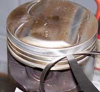
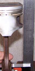
This will require a little bit of improvisation as I am sure you won't have the correct alignment tool. The correct tool checks for twist as well but this test only checks for a side bend. A right angle steel square will do the job as long as it is a perfect right angle. Place the big-end journal on the square and slide the assembly until the piston almost touches the rule. Now look to see if the top section of the piston above the gudgeon pin is square with the edge. If the piston
is closer at the top than the bottom, then the rod is bent. Rotate the assembly 180 deg and check again. The bent will now be the other way. If it is not then the ruler is not square or you are not placing it correctly or squarely on the base of the square. Re-check again.
|
|
|
|
|
Big-end Bearing Crush & Oil Clearances
|
|
| |
|
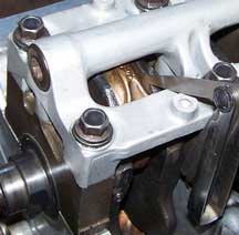
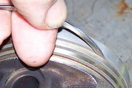
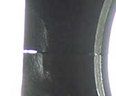
In this engine removing the con-rod caps to check clearances is difficult due to the main bearing cap girdle design. It is done exactly the same as the mains. Once again it is much easier in this instance to use a micrometer and inside gauges to measure the clearance. The crush is done just like the mains. Hold the conrod in a vice then torque up the nuts. Loosen one side and fit the largest feeler gauge into the gap close to the bearing. In the close up, you can see the gap created
from the proper amount of crush. Mine was .007" spot on. Remember to check the measurement close to the bearing shell.
|
|
|
|
|
Fitting Rings to Pistons
|
|
| |
|
You can use your fingers to spread the rings but it gets really hard after you have done a few and the risk of breaking a ring is slightly higher. Every ring set I have ever fitted has been by following the instructions on the box. It tells you how to space the oil ring segments, which way up to fit the rings and where to set the top and second ring gaps. Pretty easy.
|
|
|
|
|
Fitting Pistons into Block
|
|
| |
|
|
|
Final Torquing and Rotation Test
|
|
| |
With the last piston fitted and conrod torqued, rotate the engine over a few more times to check for smooth rotation. When the pistons roll over TDC & BDC the effort required to turn the engine will be significantly less than when they are half way up or down. This is normal and should not be considered as binding. |
|
|
Preparing Oil Pump & Fitment
|
|
| |
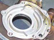 |
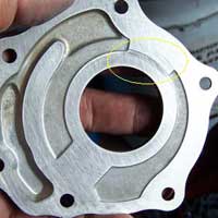
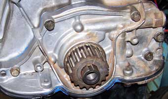
I have left the oil pump fitment as late as possible to preserve the priming of the pump. The next time I rotate the engine is after the cylinder head is fitted. There will be oil in the sump and any further turning of the engine will aid in priming the oil pressure prior to starting the engine once it is fitted. Photo on left shows where the pump cover has not been sealing. Using 400 grit wet & dry paper, this surface needs to be surface ground. |
|
The cover plate needs to be surfaced using 400 grit paper. Deep gouge marks cannot be removed. I am just trying to ensure the cover will seal on the outer edges against the oil pump housing. No sealer is used between the parts so both parts need to be flat.
|
|
|
|
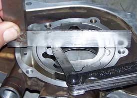
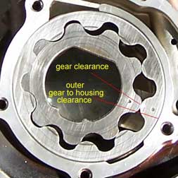
Check gear side clearance. Place straight edge across pump housing and measure the gap between the gears and straight edge. All clearances will be stated in the workshop manual. If gap is too tight, just surface the gears on 80 grit paper then finish off on 400 grit until desired clearance is obtained. If the clearance is to much, it indicates wear, replace the pump.
|
|
|
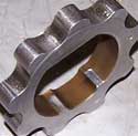
A normal feeler gauge cannot be used to measure the outer gear to housing clearance. If you don't have a thin gauge set measure the bore and gear and subtract to find the clearance.
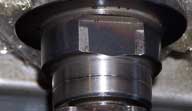
(left photo) Check the wear on the inner gear where it is driven by the crankshaft. Discard the pump if badly worn. Once all the clearances have been checked it is in for a final clean and assembly can begin.
|
|
Lubricate all the pump gears with pre-assembly lube and add extra lube in between the gaps in the gears. Fit the cover plate and torque it to specs. Apply grease to the seal lip and to the mating surface on the crank. Apply a thin smear of sensor safe silicone to the joining face ensuring the O' ring is fitted to the pump before fitting it to the block. Apply a small amount of sealant where the sump meets the cover as seen in the photo.
|
|
|
Fit Ancillary Items & Sump
|
|
| |
|
Take note that the torque on the centre bolt of the oil cooler has very little torque applied, less in fact than the sump bolts. Don't over torque it. The problem with such little torque is that the bolt may come undone when removing the oil filter and this will make it difficult to re-assemble the cooler while the engine is installed. The solution is to Loctite the bolt and don't over tighten the oil filter. You only need to tighten the filter the recommended amount as directed
on the oil filter.
|
|
|
|
| Cylinder head |
|
| |
Once the head is re-assembled, ensure the number one piston is on exact TDC before fitting the cylinder head on. Also ensure the two mating surfaces are exceptionally clean and flat. I hope you cleaned the head bolt threads by this stage. Now place a few drops of oil on the bolt thread and some pre-lube under the bolt head and washer. Now here is a note to remember. My specification sheet only mentions to torque the cyl head in two stages, however the instructions that came
with the head gasket set was totally different. I went with the instruction that came with the head gasket kit. It recommended 4 stages. Stage 1, 2 & 3 were just incremental torques with 3 being the final torque. The fourth step was to back off the bolt 90 deg and then re-torque to maximum again. Whatever brand of gasket you choose to use, I would follow what the manufacturer of the gasket says. |
|
| |
|
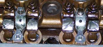
When installing the rocker gear ensure you put plenty of pre-assembly lube on all the rocker components. Lube the camshaft lobes and fit the cams to the timing marks. Fit the timing belt and then set the tappets. Continue to assemble all the last bits and pieces.
All done. Now bolt up a transmission and fit the engine back in the car.
|
|
|
|
|
Final Checks
|
|
| |
Some points before starting the engine.
- Check engine oil and water levels
- Pressure test the cooling system if possible
- Ensure the battery is fully charged
- Disable the ignition or fuel injectors
- Remove the spark plugs
- Turn ignition on and make sure the oil warning light is illuminated
- Crank the engine until the oil light goes out and continue to crank for another 5 seconds. STOP if you hear any unusual sounds that should not be there.
- Refit the spark plugs and re-enable the ignition or fuel system as necessary
- Start the engine, it should fire immediately. A few seconds after the oil light goes out take the engine to 2000 RPM and hold for 30 seconds.
- Check for oil leaks and water leaks if you did not pressure test the system.
- Take it out on the road to bed the rings in, by the time you come back the rings will be bedded and if you flex-honed the bore it will be run in, unless you chose to deliberately build a tight clearance engine. In this case take it easy for about 1000 Km's.
- Do a final check and adjust anything necessary, check ignition timing and reset if necessary, re-adjust idle speed.
- In 500 Km change the oil & filter, reset the tappets. I would also recommend at this stage to add a friction modifier to the oil.
|
|
| |
Hopefully if you were diligent with your assembly and didn't take any short cuts or quick fixes, then you should get the most from your new engine. Make sure you service it regularly and keep a vigilant eye on the water temperature gauge. Please read my other articles on cooling systems and overheated aluminium cylinder heads. The information in them will be useful to you. |
|